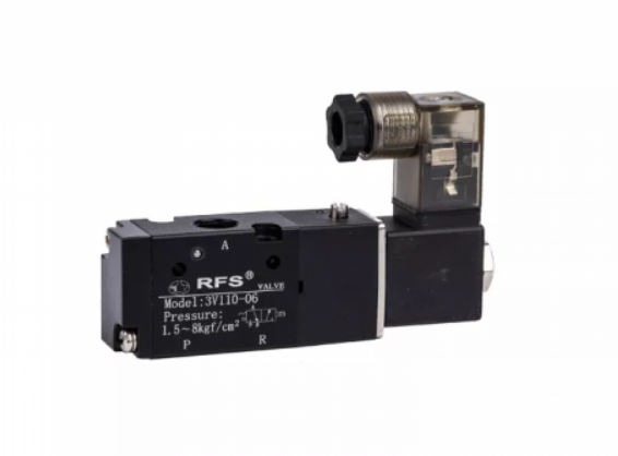
What Are Directional Control Valves, And Why Do You Need One?
One of the most fundamental and important components of any fluid power system is the directional-control valve. As the name suggests, directional control valves are used to direct the flow of fluid through the system. Directional control valves control when and where the fluid in the system flows. These valves serve to direct fluid flow in a system.
Directional control valves are used to control the direction and movement of hydraulic fluid through a system. They are often referred to as switching valves, and come in three main categories: hydraulic check valves, directional spool valves and poppet valves that make up the different types of control valves.
Things To Consider When Choosing Directional Control Valves
There are five major points to consider when it comes to analysing the performance and suitability of directional control valves:
- Dynamic Power Limits;
- Static Power Limits;
- Resistance To Flow;
- Switching Time;
- Leakage;
What Is A Hydraulic Check Valve And How Can They Be Used?
Check valves are fundamental and widely used directional control valves in hydraulic systems. They primarily serve to stop the flow of liquid in one direction while permitting unrestricted fluid flow in the opposite direction, commonly referred to as non-return valves.
In addition to their primary function, hydraulic check valves can fulfill various roles within a hydraulic system, such as:
1. Prefill-valves to prevent cavitation.
2. Bypass valves or return-line filters.
3. Blocking flow in one direction.
4. Pre-tensioning by creating backpressure in the system.
5. Protecting hydraulic components from pressure surges.
Most check valves are spring-loaded and employ a ball or plate mechanism to seal the flow in a single direction. The design of check valves ensures reliable circuit isolation without the risk of leakage. Various elements, including poppets with soft seals, can be utilized in these valves to isolate circuits effectively.
What Is A Directional Spool Valve And How Can They Be Used?
Directional control valves consist of a movable spool located within the valve housing. An actuating force shifts the control spool, facilitating the connection or separation of channels within the housing. These valves possess distinct features that make them suitable for various conditions, including:
1. Cost-effectiveness due to their simplicity.
2. Low actuating force requirements.
3. High switching power.
4. Low-level losses, despite consistent oil leakage.
Related links:How to Quickly Repair a Bad Valve Seal?
Understanding the Sanitary IDF Union: Key Insights
4 Tips to Select the Perfect Yoga Studio
How Forklift Carton Clamps Revolutionize Warehouse Efficiency?
Key Questions to Ask When Choosing a Forklift Side Shift Attachment
How Does a 4-Way Ball Valve Function?
How to Choose a 28mm Pump Gate Valve?
5. Diverse control functions for operator convenience.
These valves can be either directly-operated or pilot-operated. They may be connected with solenoids or mechanically controlled through levers, rollers, or hydraulic and pneumatic systems.
What Are Directional Poppet Valves?
These control valves, commonly known as cartridge valves, are installed in housing bores using a threaded connection. They are well-suited for operating conditions up to 1,000 bar and can incorporate various seating elements such as balls, poppets, and plates.
Key features that enhance their utility include:
1. Leak-free operation.
2. Extended and reliable product lifespan.
3. High maximum operating capacities.
4. Excellent sealant characteristics.
Their design enables these valves to achieve tighter sealing as the operating pressure increases. However, their maximum flow is often limited compared to other control valves, making them less suitable for systems requiring high flow rates.
How Directional Control Valves Work
Directional control valves are chosen based on their ability to handle system pressure, allowing for a shift from fully open to closed or proportionally. This shift can happen instantly, causing rapid fluid acceleration and deceleration. In the case of proportional valves, modulation is employed to control the acceleration and deceleration of actuators, either manually or automatically through preset cycles. These valves keep fluid in standby mode, preventing its flow within the system until needed for a specific function.
When activated, directional control valves swiftly shift to perform their designated operation and return to the neutral position upon completion. This instantaneous action accelerates and decelerates fluid as required. The simplest form of directional control valve is the 2-way valve, capable of either stopping or allowing flow. A 2-way valve consists of two ports – the inlet and the outlet. An analogy for a 2-way valve is a water faucet, showcasing its straightforward control of flow by manual adjustment.
When selecting a directional control valve, designers consider two primary characteristics: fluid ports and the number of positions. Valve ports serve as passageways for hydraulic fluid to flow to or from other components, while the number of positions indicates the distinct flow paths a valve can provide, such as Forward, Neutral, or Reverse.
Selecting a Directional Control Valve
Directional control valves are categorized based on various characteristics, including the maximum flow rate, maximum rated working pressure, number of ports, number of positions, actuating method, fluid path, leakage rates, and more. Here's a breakdown:
1. Max Flow Rate/Max Rated Working Pressure: Indicates the maximum pressure required for the valve to perform its work in the process.
2. Fluid Path: Examples include 2-way 2-position valves, like check valves, which are actuated by line pressure to allow free fluid flow in one direction or block flow in the opposite direction. Shuttle valves, on the other hand, are examples of 3-way 2-position valves, allowing switching from two ports into one common circuit.
3. Positions: Typically, valves have two or three positions – Forward, Neutral, Reverse.
4. Ports: The number of flow paths through which fluid can enter and exit the valve.
5. Actuation: Refers to how the valve is cycled.
These characteristics help define the specific functionality and application of directional control valves in hydraulic systems.
Related links:How Does Concrete Overhead Block Clamp for ODM Work?
How to Choose the Right Overhead Block Clamp for Concrete ODM?
Why Choose Three-Quarter-Inch Ball Valves Over Others?
Top 5 Benefits of 160mm Gate Valve Explained
Design and Construction of ABB Low Voltage Motors
Top Gray and Ductile Iron Castings Services Explained
Top Quality Ductile Iron Casting for Sale Today!


